- 您现在的位置:买卖IC网 > Sheet目录3887 > PIC16F84AT-20E/SS (Microchip Technology)IC MCU CMOS 20MHZ 1K FLSH 20SSOP
PIC16F84A
DS35007B-page 76
2001 Microchip Technology Inc.
APPENDIX B:
CONVERSION CONSIDERATIONS
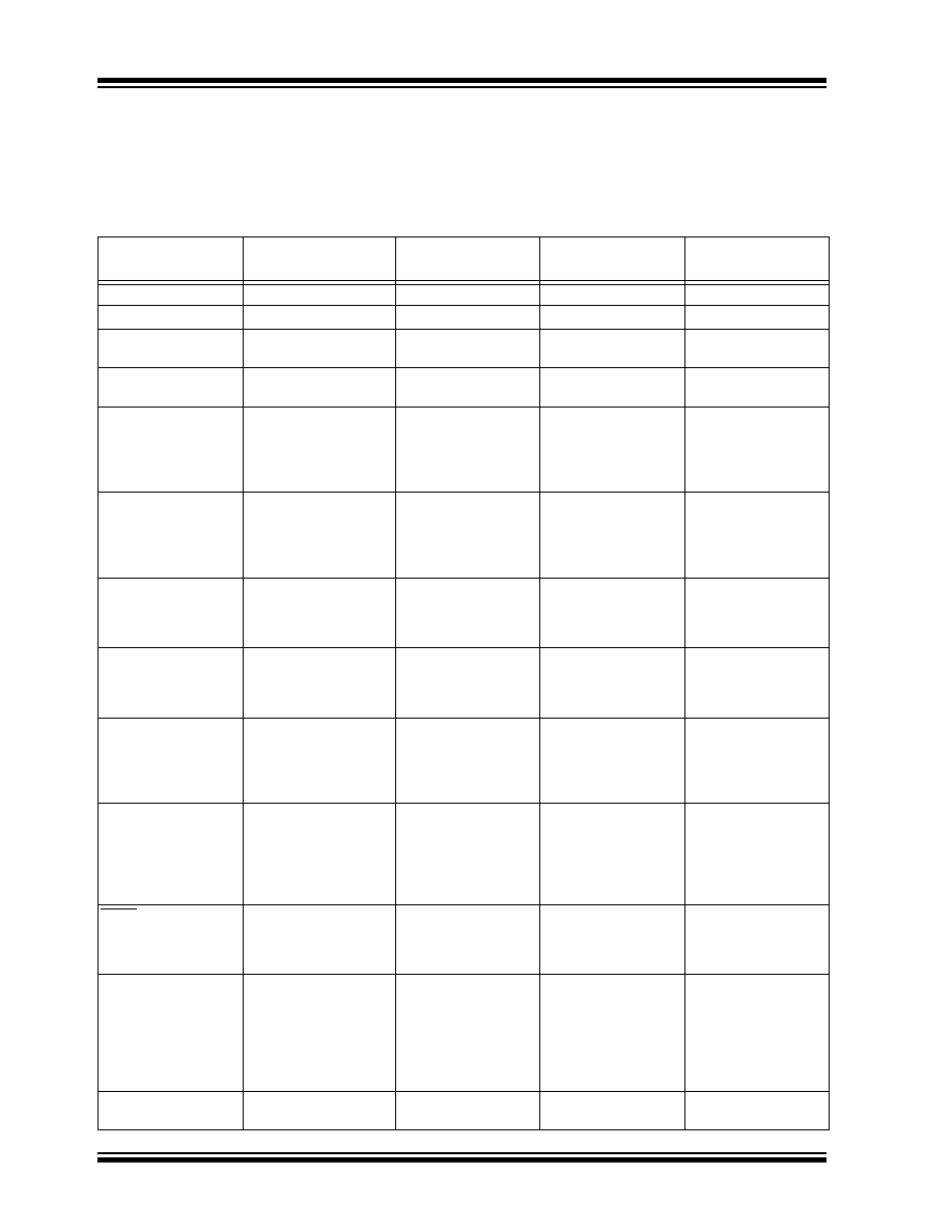
Considerations for converting from one PIC16X8X
device to another are listed in Table 1.
TABLE 1:
CONVERSION CONSIDERATIONS - PIC16C84, PIC16F83/F84, PIC16CR83/CR84,
PIC16F84A
Difference
PIC16C84
PIC16F83/F84
PIC16CR83/
CR84
PIC16F84A
Program Memory Size
1K x 14
512 x 14 / 1K x 14
1K x 14
Data Memory Size
36 x 8
36 x 8 / 68 x 8
68 x 8
Voltage Range
2.0V - 6.0V
(-40
°C to +85°C)
2.0V - 6.0V
(-40
°C to +85°C)
2.0V - 6.0V
(-40
°C to +85°C)
2.0V - 5.5V
(-40
°C to +125°C)
Maximum Operating Fre-
quency
10 MHz
20 MHz
Supply Current (IDD).
See parameter # D014 in
the electrical specs for
more detail.
IDD (typ) = 60
A
IDD (max) = 400
A
(LP osc, FOSC = 32 kHz,
VDD = 2.0V,
WDT disabled)
IDD (typ) = 15
A
IDD (max) = 45
A
(LP osc, FOSC = 32 kHz,
VDD = 2.0V,
WDT disabled)
IDD (typ) = 15
A
IDD (max) = 45
A
(LP osc, FOSC = 32 kHz,
VDD = 2.0V,
WDT disabled)
IDD (typ) = 15
A
IDD (max) = 45
A
(LP osc, FOSC = 32 kHz,
VDD = 2.0V,
WDT disabled)
Power-down Current
(IPD). See parameters #
D020, D021, and D021A
in the electrical specs for
more detail.
IPD (typ) = 26
A
IPD (max) = 100
A
(VDD = 2.0V,
WDT disabled, industrial)
IPD (typ) = 0.4
A
IPD (max) = 9
A
(VDD = 2.0V,
WDT disabled, industrial)
IPD (typ) = 0.4
A
IPD (max) = 6
A
(VDD = 2.0V,
WDT disabled, industrial)
IPD (typ) = 0.4
A
IPD (max) = 1
A
(VDD = 2.0V,
WDT disabled, industrial)
Input Low Voltage (VIL).
See parameters # D032
and D034 in the electrical
specs for more detail.
VIL (max) = 0.2VDD
(OSC1, RC mode)
VIL (max) = 0.1VDD
(OSC1, RC mode)
VIL (max) = 0.1VDD
(OSC1, RC mode)
VIL (max) = 0.1VDD
(OSC1, RC mode)
Input High Voltage (VIH).
See parameter # D040 in
the electrical specs for
more detail.
VIH (min) = 0.36VDD
(I/O Ports with TTL,
4.5V
≤ VDD ≤ 5.5V)
VIH (min) = 2.4V
(I/O Ports with TTL,
4.5V
≤ VDD ≤ 5.5V)
VIH (min) = 2.4V
(I/O Ports with TTL,
4.5V
≤ VDD ≤ 5.5V)
VIH (min) = 2.4V
(I/O Ports with TTL,
4.5V
≤ VDD ≤ 5.5V)
Data EEPROM Memory
Erase/Write cycle time
(TDEW). See parameter #
D122 in the electrical
specs for more detail.
TDEW (typ) = 10 ms
TDEW (max) = 20 ms
TDEW (typ) = 10 ms
TDEW (max) = 20 ms
TDEW (typ) = 10 ms
TDEW (max) = 20 ms
TDEW (typ) = 4 ms
TDEW (max) = 8 ms
Port Output Rise/Fall
time (TioR, TioF). See
parameters #20, 20A,
21, and 21A in the elec-
trical specs for more
detail.
TioR, TioF (max) = 25 ns
(C84)
TioR, TioF (max) = 60 ns
(LC84)
TioR, TioF (max) = 35 ns
(C84)
TioR, TioF (max) = 70 ns
(LC84)
TioR, TioF (max) = 35 ns
(C84)
TioR, TioF (max) = 70 ns
(LC84)
TioR, TioF (max) = 35 ns
(C84)
TioR, TioF (max) = 70 ns
(LC84)
MCLR on-chip filter. See
parameter #30 in the
electrical specs for more
detail.
No
Yes
PORTA and crystal oscil-
lator values less than
500 kHz
For crystal oscillator con-
figurations operating
below 500 kHz, the device
may generate a spurious
internal Q-clock when
PORTA<0> switches
state.
N/A
RB0/INT pin
TTL
TTL/ST*
(*Schmitt Trigger)
TTL/ST*
(*Schmitt Trigger)
TTL/ST*
(*Schmitt Trigger)
发布紧急采购,3分钟左右您将得到回复。
相关PDF资料
PIC16F84AT-20E/SO
IC MCU CMOS 20MHZ 1K FLSH 18SOIC
22-15-3133
CONN FFC/FPC 13POS .100 RT ANG
PIC16F84AT-04E/SS
IC MCU CMOS 4MHZ 1K FLASH 20SSOP
22-02-3133
CONN FFC/FPC VERTICAL 13POS .100
PIC16F84AT-04E/SO
IC MCU CMOS 4MHZ 1K FLASH 18SOIC
22-15-3123
CONN FFC/FPC 12POS .100 RT ANG
22-02-3123
CONN FFC/FPC VERTICAL 12POS .100
PIC16F84A-20E/SS
IC MCU CMOS 20MHZ 1K FLSH 20SSOP
相关代理商/技术参数
PIC16F84AT-20I/SO
功能描述:8位微控制器 -MCU 1.75KB 68 RAM 13 I/O 20MHz IndTemp SOIC18 RoHS:否 制造商:Silicon Labs 核心:8051 处理器系列:C8051F39x 数据总线宽度:8 bit 最大时钟频率:50 MHz 程序存储器大小:16 KB 数据 RAM 大小:1 KB 片上 ADC:Yes 工作电源电压:1.8 V to 3.6 V 工作温度范围:- 40 C to + 105 C 封装 / 箱体:QFN-20 安装风格:SMD/SMT
PIC16F84AT-20I/SS
功能描述:8位微控制器 -MCU 1.75KB 68 RAM 13 I/O RoHS:否 制造商:Silicon Labs 核心:8051 处理器系列:C8051F39x 数据总线宽度:8 bit 最大时钟频率:50 MHz 程序存储器大小:16 KB 数据 RAM 大小:1 KB 片上 ADC:Yes 工作电源电压:1.8 V to 3.6 V 工作温度范围:- 40 C to + 105 C 封装 / 箱体:QFN-20 安装风格:SMD/SMT
PIC16F84T-04/SO
功能描述:8位微控制器 -MCU 1.75KB 68 RAM 13 I/O RoHS:否 制造商:Silicon Labs 核心:8051 处理器系列:C8051F39x 数据总线宽度:8 bit 最大时钟频率:50 MHz 程序存储器大小:16 KB 数据 RAM 大小:1 KB 片上 ADC:Yes 工作电源电压:1.8 V to 3.6 V 工作温度范围:- 40 C to + 105 C 封装 / 箱体:QFN-20 安装风格:SMD/SMT
PIC16F84T-04I/SO
功能描述:8位微控制器 -MCU 1.75KB 68 RAM 13 I/O RoHS:否 制造商:Silicon Labs 核心:8051 处理器系列:C8051F39x 数据总线宽度:8 bit 最大时钟频率:50 MHz 程序存储器大小:16 KB 数据 RAM 大小:1 KB 片上 ADC:Yes 工作电源电压:1.8 V to 3.6 V 工作温度范围:- 40 C to + 105 C 封装 / 箱体:QFN-20 安装风格:SMD/SMT
PIC16F84T-10/SO
功能描述:8位微控制器 -MCU 1.75KB 68 RAM 13 I/O RoHS:否 制造商:Silicon Labs 核心:8051 处理器系列:C8051F39x 数据总线宽度:8 bit 最大时钟频率:50 MHz 程序存储器大小:16 KB 数据 RAM 大小:1 KB 片上 ADC:Yes 工作电源电压:1.8 V to 3.6 V 工作温度范围:- 40 C to + 105 C 封装 / 箱体:QFN-20 安装风格:SMD/SMT
PIC16F84T-10I/SO
功能描述:8位微控制器 -MCU 1.75KB 68 RAM 13 I/O RoHS:否 制造商:Silicon Labs 核心:8051 处理器系列:C8051F39x 数据总线宽度:8 bit 最大时钟频率:50 MHz 程序存储器大小:16 KB 数据 RAM 大小:1 KB 片上 ADC:Yes 工作电源电压:1.8 V to 3.6 V 工作温度范围:- 40 C to + 105 C 封装 / 箱体:QFN-20 安装风格:SMD/SMT
PIC16F870-E/SO
功能描述:8位微控制器 -MCU 3.5KB 128 RAM 22 I/O RoHS:否 制造商:Silicon Labs 核心:8051 处理器系列:C8051F39x 数据总线宽度:8 bit 最大时钟频率:50 MHz 程序存储器大小:16 KB 数据 RAM 大小:1 KB 片上 ADC:Yes 工作电源电压:1.8 V to 3.6 V 工作温度范围:- 40 C to + 105 C 封装 / 箱体:QFN-20 安装风格:SMD/SMT
PIC16F870-E/SP
功能描述:8位微控制器 -MCU 3.5KB 128 RAM 22 I/O RoHS:否 制造商:Silicon Labs 核心:8051 处理器系列:C8051F39x 数据总线宽度:8 bit 最大时钟频率:50 MHz 程序存储器大小:16 KB 数据 RAM 大小:1 KB 片上 ADC:Yes 工作电源电压:1.8 V to 3.6 V 工作温度范围:- 40 C to + 105 C 封装 / 箱体:QFN-20 安装风格:SMD/SMT